![]() In the early days of networking splitting a network into segments required a router.
In the early days of networking splitting a network into segments required a router.
VLANS or Virtual LANS is a technology that allows you to split a home network into segments using low cost switches.
Generally a switch will send broadcast traffic to all connected ports, and will allow devices connected on any port to communicate with any other device.
VLANS were created in order to reduce the amount of broadcast traffic on a network.
However on home networks they are used mainly to improve network security.
How Do VLANs Work
If we consider a switch with 8 ports as shown in the schematic below.
A broadcast sent from a device attached to any port will be sent to all ports.
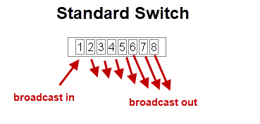
In addition any device attached to any port can communicate with any other device attached to any port.
This becomes problematic when you have untrusted devices with access to your network or as in the case of home automation you have IOT devices that are possibly vulnerable to attack.
However with a VLAN capable switch it is possible to restrict broadcasts and to control which devices can communicate with each other.
This makes it possible to design a more secure home network.
If we now take out 8 port switch and split it into two VLANs which we call VLAN1 and VLAN2 as shown below.
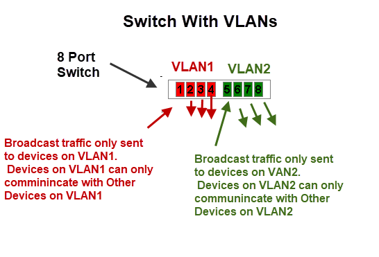
In this configuration we effectively have created two independent networks.
Devices connected to VLAN1 cannot communicate with devices that are connected to VLAN2 and vice versa.
To accomplish this the switch maintains tables of VLANs and MAC addresses.
Just as in normal switch operation it knows the MAC address of the device connected to each port and in VLAN mode it knows to only send the packet to a device with a MAC address on the same VLAN.
VLAN Uses on A Home Network
On Home networks the main use is for security where you want to isolate certain devices from each other.
You will need to choose which devices to use to implement your VLAN and the VLAN mode to use.
VLANs are supported on routers (not all) and on network switches.
On routers the VLANS have different IP subnets.
VLAN Modes
Most devices will support multiple VLAN modes.
The TP link smart switch(TL-SG105E) supports three modes:
- MTU VLAN (Multi-Tenant Unit VLAN)
- Port Based VLAN
- 802.1Q VLAN
which mode you need to use will depend on your network requirements.
MTU VLAN (Multi-Tenant Unit VLAN)
This uses a shared uplink port that is normally connected to the Internet.
The other ports can send and receive data on the uplink port but not between each other as shown in the schematic below:
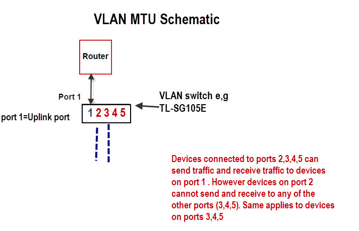
This is very easy to configure as all you really need to do is choose the uplink port (shared port) and enable it.
For example it can be used to:
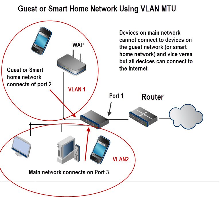
- Create an isolated guest network.
- create an Isolated smart home network.
The schematic below shows the basic layout:
Port Based VLANS
In this mode a VLAN can consist of several ports but a port can only exist on one VLAN.
It is used when you want to create an isolated network.
A possible configuration is shown in the schematic below:
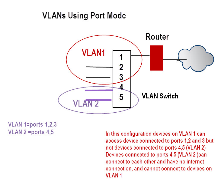
In this configuration devices on VLAN 1 can access device connected to ports 1,2 and 3 but not devices connected to ports 4,5 (VLAN 2).
Devices connected to ports 4,5 (VLAN 2 ) can connect to each other and have no internet connection, and cannot connect to devices on VLAN 1
802.1Q VLAN
This is the most flexible mode but also the most difficult one to configure.
The IEEE 802.1Q protocol defines a new format for the Ethernet data frame by inserting a VLAN tag in the data frame data frame as shown in the schematic below:
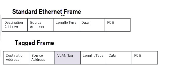
Tagging is used when you have multiple VLAN switches and a distributed VLAN.
As an example imagine you had devices in the living room connected to a smart switch and devices in a home office connected to a second smart switch.
Now you want some devices in the living room to be on the same VLAN.
Because they are physically connected to two different switches you will need to used tagging.
Because this is more complex I will cover it in its own tutorial at a later date but TP-Link include it as an example here.
For this tutorial we will take an example of a single switch with no tagging and configure two VLANs (main and guest ) with both VLANs able to connect to the Internet.
The following schematic is a modified schematic taken from the TP-Link site here.
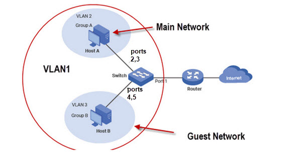
Although we have only two networks (guest and main) we require 3 VLANs.
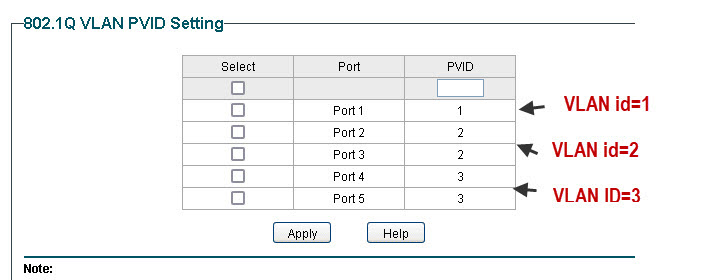
As port 1 connects the switch to the router all ports need access to this port and so we configure VLAN1 as the default to include all ports.
VLAN2 is the main network and we will use ports 1,2 and 3. VLAN3 is the guest network with ports 1,4 and 5.
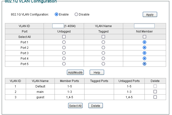
Now the not very obvious configuration is the PVID (port VLAN ID) settings which must be done for this to work the PVID must match the VLAN ID.
TP-Link Router Configuration for Guest Network
This is the configuration I use for a guest network on my home network.
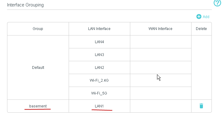
My TP-Link Router also supports VLANS, and so I connect my guest network which is in the basement to LAN1 (port1) and assign it to its own VLAN.
There is no option to assign a Wan Interface as it is automatically allowed.
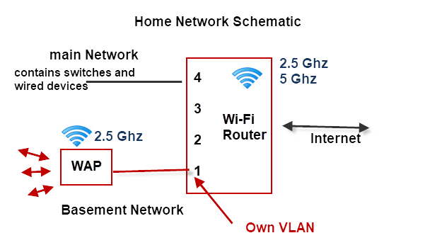
This is a schematic of my home network using the TP-link router..
Notes:
- The Wi-Fi router is on the main network VLAN.
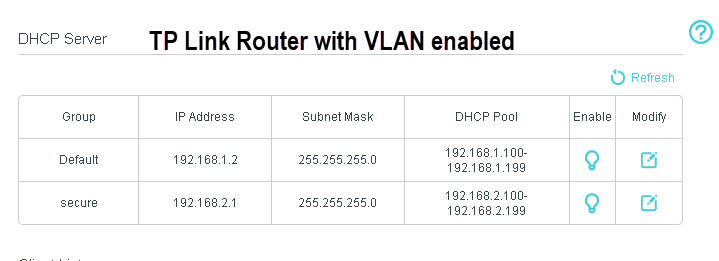
- The Router assigns a different subnet to the second VLAN. The main network uses 192.168.1.0 and the basement VLAN uses 192.168.2.0
- The basement VLAN has its own WAP
The DHCP server on the router is automatically configured to assign addresses on the new subnet as shown below:
Home Network VLAN Testing
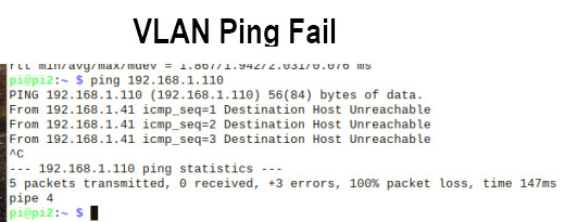
The easiest way of testing is using the ping command.
You should not be able to ping machines on different VLANs.
DHCP server Notes
The DHCP server must be located on a VLAN that is accessible by all other VLANs which usually means it is on the Internet router.
If you want a VLAN to use a separate DHCP server than the one on the router then you can install one on the VLAN without causing a problem to machines on the other VLANs.
However because a VLAN has a DHCP server it doesn’t prevent it from using the central DHCP server, and you cannot guarantee that a client on the VLAN will get the address from the local DHCP server.
Simple Home network Design Example
Example 1
You have lodgers or a guest house and want to isolate guest machines from your main network but give them access to the Internet.
Your router doesn’t support VLANs and guest Wi-Fi doesn’t have the range. You cannot change the router and both the guest and main network need Wi-Fi access
Solution
You will need a VLAN capable switch to split the network. You will also need to Wireless access points and shouldn’t use the WI-Fi provided by the main router.
A schematic is show below:
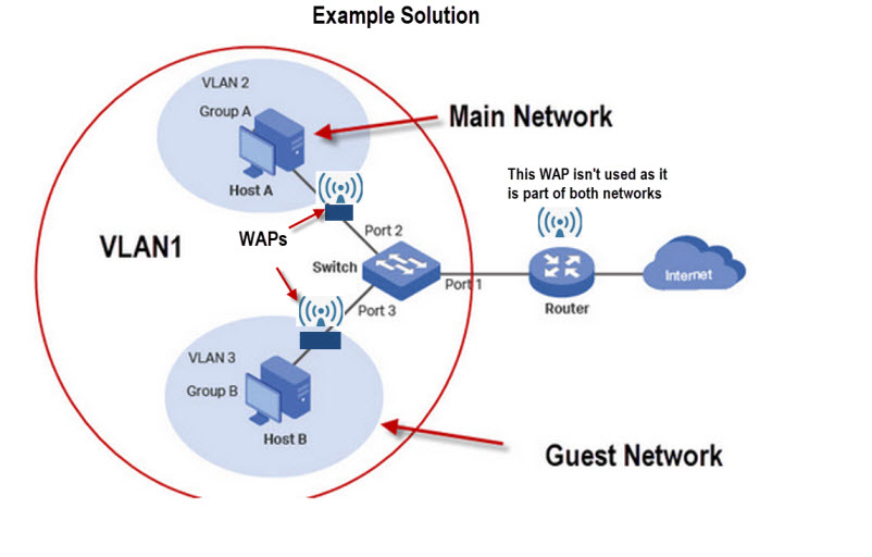
The above solution can be achieved using 802.1Q VLAN or MTU VLAN modes on the switch.
Quick Questions
Referring to the schematic for solution 1 above.
Q1- If you connect a device to the main Wi-Fi router using Wi-Fi will you be able to ping a devices on the guest and main network? Yes or No.
Q2. Will a device on the main network be able to ping a device on the main network? Yes or No.
Q3: The main router also has 3 spare Ethernet ports. Can you use them?
Q4 On what device do you think the DHCP server is located?
Answers
A1 Yes
A2 Yes
A3 If you do it will not be secure.
A4 The main router
Switches With VLAN Support
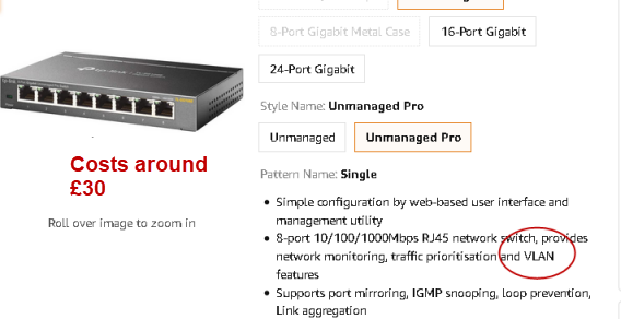
Usually if the switch is labelled as a smart switch or managed switch it will have VLAN support but you should read the description to be sure.
Below is screen shot from Amazon of a TP-link switch (£30) that supports VLANs.
VLANS vs Subnets
VLANs work on switches whereas to implement subnets you need a router.
A routed network is more difficult to setup than a switched network.
However a routed network does create separate broadcast domains while a switched network doesn’t unles you use VLANs.
The general rule is switch when you can and route when you must.
See Home Network Subnet Mask Explained
Summary
The main benefit of VLANs is that they provide an excellent and low cost method of greatly improving you home network security.
Although they also reduce broadcast traffic this is not usually necessary on a home network.
However if you have several hundred devices then this is a distinct advantage and so VLANs should be used.
Terms Used in this Tutorial
broadcast traffic– traffic that is end to all hosts(devices) on an network. Many network services rely on this type of traffic e.g ARP and DHCP.
ARP– protocol used to resolve obtain the MAC address of a device using and iP address.
DHCP– Protocol for obtaining an IP address. See Understanding DHCP on Home Networks
Related Tutorials and Resources
- How To Segment A Small LAN Using Tagged VLANs
- VLAN How To: Segmenting a small LAN
- Private VLANs -Wiki
- Basic Home Networking course
- A Beginners Guide to Proxy Servers and VPNs
- How to Create a guest Network
- How to Isolate Your Home Network from Your Smart Home Network
Steve,
Do you have an article on using the 802.Q tagging across multiple switches? So my scenario is fairly basic I would think. I purchased some budget managed switches for several rooms, each of which have devices which need to be separated. I was going to connect each of these to a master switch central to the house, next to the ISP router. The VLANs do not need to talk to one another, but they all need internet access. After doing some research, it would seem this is way more involved than using a single switch. I have read I need an L3 capable switch or a more capable router, using different subnets for each VLAN. Honestly I find it hard to believe it really takes this much hardware and configuration for what I would think is a basic and common scenario. Is it possible I am making this too difficult? I really don’t want to change the router. I would prefer to put a more capable (L3?) switch between the router and other switches. But finding this switch is difficult, given I really don’t know what I need. I was wondering if you have a writeup on this type of scenario? Any guidance you can provide would be great.
Thanks Steve,
Sean
Sorry for the late reply as I’ve been busy with website issues.
Just to clarify you have
switch1->switchA–>router
switch2–>switchA–> router
type of setup. Is that correct. What switches are they? as the VLAN capabilities vary.
Rgds
Steve
Have you done any measurements to show that broadcasts are a problem for home networks and that learning bridges aren’t adequate? I’ve got 300 endpoints and the only delays are for Wi-Fi devices. The problem of carefully managing VLANs is unbounded complexity. The irony is that if you have enough deices for broadcast to be a problem, the complexity of management problems caused by having to carefully manage the topology of the endpoints is very high.
Bob
No I haven’t done any tests myself. But I would use VLans more for security than because of broadcasts.
You can crudely check your network using the ping command as it shows the round trip delay on the network.
I wouldn’t expect broadcasts to be a problem on a home network.
Rgds
Steve
Anthony
Regarding Point 2:
If you have nothing but managed switches in your network, you can divide all the traffic into their own VLANs on the switches. The disadvantage to doing this would be that none of your VLANs on one switch could talk to the VLANs on any of the other switches. This is handy if you’re setting up a network where there is absolutely no need for the hosts to connect to the internet/other VLANs. In order to have the VLANs talk you have to have routing capabilities that L2 switches do not offer. L3 switches CAN route traffic. If you have managed switches to setup the VLANs, you can connect the various VLANs by having everything forwarded to the router via the uplink. There’s no “dumb” router that I’m aware of. There are dumb switches (L2) and intelligent L3 switches that double as routers. As for managed switches and VLAN-aware routers, it comes down to how you want to setup your network. You can have your VLAN-aware router setup with say 4 logical VLANs that use up all the ports in the back of a 4 port router. You can then take and put 1 switch on each of those you’ve made and divide those down into smaller networks. The disadvantage of doing this is it makes the network very complex and takes time to setup and if you get lost along the way it could make it where the devices can’t connect. It also makes it to where none of the traffic can go to the other VLANs without punching holes in the firewall that would allow various devices to connect to their destination. So that adds another variable into the already complex network, but there are use-cases to setting up a network in this way, particularly in enterprise settings (which would offer more than just those 4 ports on the router in most cases) which means it gets even MORE complex as you grand/deny permissions.
Cheers,
Jeremy
Jeremy
Tks for the rather detailed and informative comment. My approach is to keep it as simple as possible and adding VLANs makes it complex and as you say the more you add the more complex it gets.
On home networks were the person configuring it is not normally a networking professional then it is best to keep it as simple as possible. For most home networks wi_fi guest networks generally suffice.
Rgds
Steve
Hi, which is the TPLink router you use which supports VLAN? I suppose if possible, it is preferable to get a new router rather than a switch / wireless AP combo?
Thanks
It is a Archer vr400 but I guess all the new ones support Vlans. Whether you need a router or switch depends on what setup you have.
Rgds
Steve
thanks
Thank you for the article, it is very informative and well written !
I have a question about the examplary configuration at the end – with router which does not support vlans and a managed switch:
What would happen if a host in guest network vlan (Attacker Host) tries to reach a host in the main network vlan (Vicitim host), and knows the IP.
My thinking is – Attacker Host will send ARP for the Victim Host IP and no response will be received (obviuosly since the hosts are not in the same broadcast domain) so the Attacker Host will send the packet to the default gateway. The Router will receive the packet, recognize the Victim Host IP (all the IPs were assigned by the DHCP server on the router) and send the packet back on the same port with the ethernet frame modified to reach the Victim Host.
The packet enters port 1 on switch and is forwarded by the switch to the Victim Host.
I think I must be missing something here because I’ve seen the same solution (vlan capable switch + non-vlan router) described on other websites and no security risks like that have been mentioned.
Any help will be appreciated.
Thank you.
I assume you are referring to the very last diagram.Generally VLANs on switches use MAC addresses and not IP addresses so filtering is done on the Mac address and not the IP address.The router routes on network address and in this case they are the same and so the router just drops the packet.
Even if address resolution was successful then the mac address filtering still applies so you wouldn’t expect it to work.
Rgds
steve
Yes, I am referring to that last diagram.
The problem I see with that explanation is:
1. Regarding the IP address resolution on the router:
The IP addresses of the host machines in VLAN2 and VLAN3 would not be the same. They would be in the same subnet, assigned by the DHCP server on the router. My understanding is that if HostB sends a packet to the default gateway (the router) with destination IP of HostA then the router would have the IP in its routing table and would route the packet down the same port it received it. I don’t think there’s any reason the packet would be dropped (the scenario assumes a “dumb” router so no extra routing rules).
2. MAC filtering on the switch:
In the discussed scenario the MAC address on the frame sent to switch from the router would be the Router MAC address so no filtering rules would apply as traffic between Port 1 and Port 2 is allowed.
Unfortunately I don’t have the HW to confirm this behavior in real use-case, but due to the aforementioned reasons I think such setup would not work as advertised and is insecure.
If my assumptions are not correct I’d be happy to find out the exact reasons.
I was going to go ahead with such setup for my home network but now I think I’ll just by a L3 smart switch which would handle DHCP / subnets / routing between the Vlans.
Regards,
Peter
Sorry but I should have been more explicit. I think the diagram is the same as worked example 1 using the switch and no vlans on the router.
In this case there is only one subnet. at it should work as described and I’m pretty sure I tried it when I wrote the tutorial but it was a little while ago.
Rgds
Steve
Great article Steve. Thanks!
2 things, though:
1. In your 802.1Q example, its not clear to me why we need vlan1 to encompass all the ports. Wouldn’t only port 1 be sufficient? (This makes it now seem that Host B is on both VLAN3 and VLAN1 at the same time. It looks like we “clear that up” by assigning PVIDs, but I’m just wondering why vlan1 needs port 1-5 when you end up assigning only pvid1 to port1, anyway.)
2. What’s the advantage of using a vlan-capable router with vlan switches? (I think I know: the ability to route vlan-tagged frames) but I guess what I’m asking is: what type of traffic “routing” (even if it’s just within the same switch) can you accomplish with devices under these 3 scenarios:
– nothing but managed switches (no routers)
– managed switches and a dumb router
– managed switches and a vlan-aware router
Thanks again!
I agree with you regarding port 1 and I set it up without port 1 only to find it didn’t work and then I read the manual.
As to point 2 I will need to have a think and I will put it into the tutorial
rgds
steve