 What is Power over Ethernet (PoE)?
POE allows an Ethernet cable to carry DC power as well as data signals to attached devices.
It is used for connecting remote devices that don’t have a convenient local power source like IP cameras, VOIP phones etc.
Ethernet Cable Basics and POE Wiring
Ethernet cable (CAT 5,6 &7) uses 4 twisted pairs. On early Ethernet networks operating using 10base T and 100base TX only 2 pairs were used for carrying data and the other two were spare.
These two spare pairs can be used for carrying DC power. In the IEEE 802.3 standard this is known as Alternative B mode.
As Ethernet speeds increased (1000Base T and above) then it became necessary to utilise all 4 pairs to carry data.
So to supply DC power you needed to supply power over pairs that were also being used for carrying data.
Because it is DC power this is relatively easy to do.
Alternative A mode was defined which sent power over the same cable pairs as used in !0Base T to carry data.
In both cases only two pairs are being used for carrying DC power.
This is shown in the schematic below:
As the requirement for more DC power for end devices increased a third mode was defined called 4PPoE which uses all 4 pairs to carry DC power.
POE Voltages and Standards
PoE as defined in IEEE 802.3 standard supplies power at 47V – 57 Volts DC. The difference in the standards is the amount of power that can be provided to end devices.
There are 4 standards designed to support 4 device types .
- 802.3af (Type1 )-Up to 15.4W
- 802.3at -(Type2 – known as PoE+) Up to 30W
- 802.3bt -(Type3 – known as 4PPoE) Up to 60.W
- 802.3bt -(Type3 – known as 4PPoE) Up to 100W
POE Device Types
Power Source equipment (PSE) supplies power to end devices. Typical devices are switches and routers.
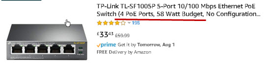
You should notice in the screen shot that it clearly states that it supports POE.
Powered Devices (PD) – These consume power provided by PSEs.
PDs must work in both Alternative A and Alternative B modes. Typical devices are cameras and Wireless access points.
The PSE determines which mode to use.
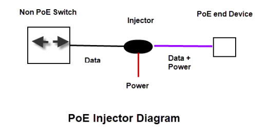
PoE Injector – These are used to connect a PoE end device to a non PoE device like a legacy switch.
The legacy switch cannot provide the power so the injector does. (schematic below)
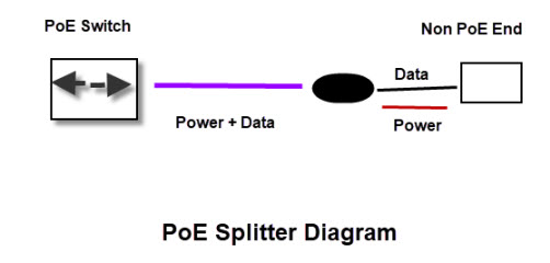
PoE Splitter – This Splits the data from the power and is used to connect a non PoE end device to PoE source. The power extracted by the splitter is often used to power the device using a separate power input.(schematic below)
Powering Equipment
Devices that are designed to meet any of the standards have built in power management.
When the end device is connected to the PSE negotiation takes place to determine how much power the device needs, and how it will be supplied.
If the PSE doesn’t detect this negotiation it doesn’t supply power.
This means that it is safe to plug a non PoE end devices into a PoE port and not experience any problems.
The following set up negotiation steps are taken from the wiki
The set up phases are as follows:
- PSE (provider) tests PD (consumer) physically using 802.3af phase class 3.
- PSE powers up PD.
- PD sends to PSE: I’m a PD, max power = X, max power requested = X.
- PSE sends to PD: I’m a PSE, max power allowed = X.
PD may now use the amount of power as specified by the PSE.
The rules for this power negotiation are:
- PD shall never request more power than physical 802.3af class
- PD shall never draw more than max power advertised by PSE
- PSE may deny any PD drawing more power than the max allowed by PSE
- PSE shall not reduce power allocated to PD that is in use
PSE may request reduced power, via conservation mode
POE Benefits
The main benefit are easy installation and cost saving as there is no need to run mains power to the device. This also means better safety as POE uses lower voltages than AC mains.
Non Standard Implementations
There are several non standard implementations but the most common one is known as passive PoE.
It is generally used to supply lower voltages (24V) but uses the same Pin out arrangements as 802.3af mode B or 802.3af Mode A for Gigabit Ethernet.
However the crucial difference is that passive devices do not negotiate with the power source and so power is always applied.
Plugging a non PoE end device into a passive PoE power source will probably destroy the end device.
PoE Video
Questions
Q- Can I power my Raspberry pi using PoE
A- Yes but you need a model 3b+ or 4 and a separate hat
Q- What is the maximum distance between PSE e.g switch and PD e.g IP camera?
A- 100m is the limit imposed by Ethernet for the data signal. You can extend this using a PoE extender/repeater.
Q -Does PoE require a special cable?
A- No it uses a standard Ethernet cable.
Q- What is the difference between 802.3 AF and 802.3 at?
A- The difference between 802.3af vs. 802.3at is the power available to the end device. 802.3af can supply 15.4 Watt and 802.3 at (POE+) can supply 25.5 Watts.
Summary
Power Over Ethernet (PoE) is a method of providing power to remote devices on a LAN using a standard Ethernet cable thus removing the need for a remote mains power supply.
It has been standardised by the IEEE but there are also vendor implementations that are non standard. The main one to be aware of is Passive PoE.
Other Tutorials: Resources:
- How to Extend a Home Network
- Powerline Networking Guide -How To Setup HomePlug Adapters
- Wiring a Home Network
- What is Power over Ethernet
- PoE Explained
- Active or Passive PoE That is the question
When calculating the max distance for ethernet cable on a PoE switch device. the the max distance split between each port? or is the max distance availible for every port?
Example… every port can support a 100 meter ethernet cable, or only 25 meters split between 4 ports?
The 100m is the ethernet cable limit and it is per port.
Rgds
Steve